How I made my engine mounts putting a duratec in my fury rebuild
So, as part of rebuilding my fury and shoving a duratec engine in, I decided to make some new engine mounts. I wanted to reduce weight and improve the packaging as well – the old mounts used up a lot of space that could otherwise be spent moving mass down – I have swirl pots and fuel pumps to put somewhere after all.
Firstly, I went to Fast Dan (DanST Engineering) and ordered some engine mount plates. They’re a great fit. I think the price is good value and there are times when buy is far better than build.
 Secondly, I decided on the design, and went for something inspired by SBDev and which gave me quite a compact result and rather contradicted the original design that was somewhat agricultural (see the picture on the right). The original design was from my previous pinto installation.
 So, here is the assembled list of bits. Rather than go for a huge rubber mount (which of course would be good for absorbing vibrations) I’ve taken a gamble on using (reusing) the bushes I’ve taken out of the suspension. I’ve fabricated everything from 32mm dia 3mm thickness CDS. The sleeve inner diameter didn’t match the bush outer diameter, so I bobbed over to a friends and put it into the lathe. It was then machined out to take the bush with a reasonable amount of slack, knowing the sleeve will clench up a little when welded.
The mounting plates needed to be notched in order to accommodate the way the plates were offset when mounted on to the chassis rail. Note that each plate is a different size to account for the angle of the rails; I wanted to feed the load into the chassis at 90 degrees, rather than an angle. An angle would mean putting some bending load to the leg from the plate to the chassis (not ideal). In order to get the hole in the correct place for the plate, I hand-fitted the sleeve and plates to the chassis, and clamped it with a welding clamp (you need a third hand for this, thank you Zaphod). Then I used a CD marker pen to draw around the sleeve, added cross-hairs after dismantling and punched a hole.
These plates are 3mm stainless (left over scrap), so you can’t just go riving at them with a 1/2 inch drill bit (the bushes are the standard, mandatory, obligatory, inexplicable 1/2″ inner diameter). I started out with a 3mm hole, and went up in increments of 2.5 or 3mm, depending on which bits I had to hand. I also found that the cobalt set of drill bits bought from tool-station started to show their value. A cheaper set of bits just screamed and blunted making virtually no impact on the hole, yet the cobalt ones cut through nicely. I also used a spray cutting-oil (and lots of it) to help things along.
 The thing you have to remember is that drill bits don’t cut round holes, and the larger the bit, the more obvious this becomes. Once I’ve got the hole out to 12mm, I then ream it out to 1/2 inch. I bought a tapered reamer from ebay for not a lot of money and it’s done me proud. It reams stainless out as well, but again, it wont go out more than 0.75mm. You can see on the right here how the hole isn’t perfect before reaming.
 Next, I needed to machine the down-leg to fit the sleeve. The sleeve was cut from the same tube I’m making the leg from, so that was at least reasonably simple to cut a matching fish-mouth. I used this software, printed it out, stuck it to the tube and got busy. I cut the majority of the metal away with a 0.8mm slitting disk, and then tidied up and ground out to the the marks using a tungsten burring tool on an air-die grinder. You can see the results yourself on the right.
 There are other things to note in setup before finally welding it together. The main one is to try and have the engine level in the chassis. It helps to keep coolant and oil levels as horizontal as possible. I used a spirit level on the back of the car to be sure the chassis was level (it was) and then put the same level on the flat gearbox top to be sure i had the engine in the right place: one can’t really take a measurement off the top of the duratec: it’s all curvy.
I found out that chocking the engine in place was tricky – the chocks were difficult to place and kept popping out. Interestingly, a run of duck-tape from the chassis rails to the top of the engine was a great way of keeping it in place (Thanks Darren – very smart move). Duck Tape is like the force – it has a light side and a dark side and it holds the universe together.
 This is what the mount looks like from the engine down to the bush:

and this is what the whole lot looks like when nailed together to try the fit. The offset between one bracket and the other is more noticeable on this side.
 Finally, this is what the almost completed installation looks like. There are a couple of points to note – I’ve put a reasonable seam in to hold the bracket facing the camera (and the one you can’t see the seam on) but I won’t be able to complete the seams until I get the engine back out. This was part of the plan – the engine is just a dry-build at the moment to be sure I have everything in the right place.
I still have one job left, which is to put a bracing plate in at 90 degrees to the bracket to tie the front-to-back loads to the chassis. I don’t think the loads will be all that significant, but they may eventually fatigue the joint. I only need one plate because the bush will transfer the load from the other bracket to the bracket with the cross-brace. It’s only going to be a few grams of steel but it’s worth getting right. Even if I’m being paranoid I’m only wasting a few grams.
Speaking of which, each mount is 500g lighter than the previous, so I’m a kilo up on the deal as well.


 So, just about the last job to do on the sump is to get the dipstick path routed up the side of the engine. As per flak’s instructions, I bought some 15mmOD stainless tubing to match the hole machined in the side of the sump. My original plan was to route the pipe vertically up the side of the engine and emerge between the throttle bodies. As you can see from the pic below, this isn’t a great route, and runs far too close to many things, including the engine mount bolts, and one of the water pump housing take-offs.
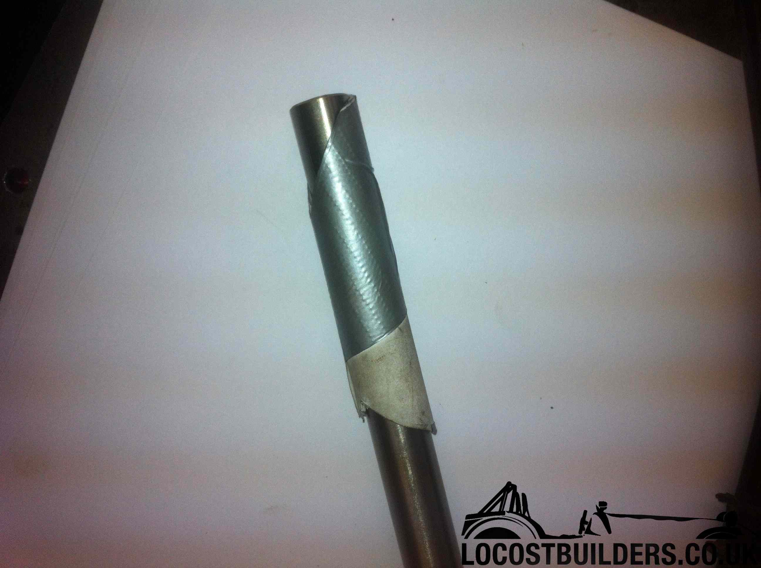 Now that I had a plan to take a route, i needed to plan the take-off from the block. Wrapping some paper around the pipe and using duck tape to make it rigid, i now had a template of the pipe that could be cut with scissors until I had the angle right without risking multiple chops into the steel.
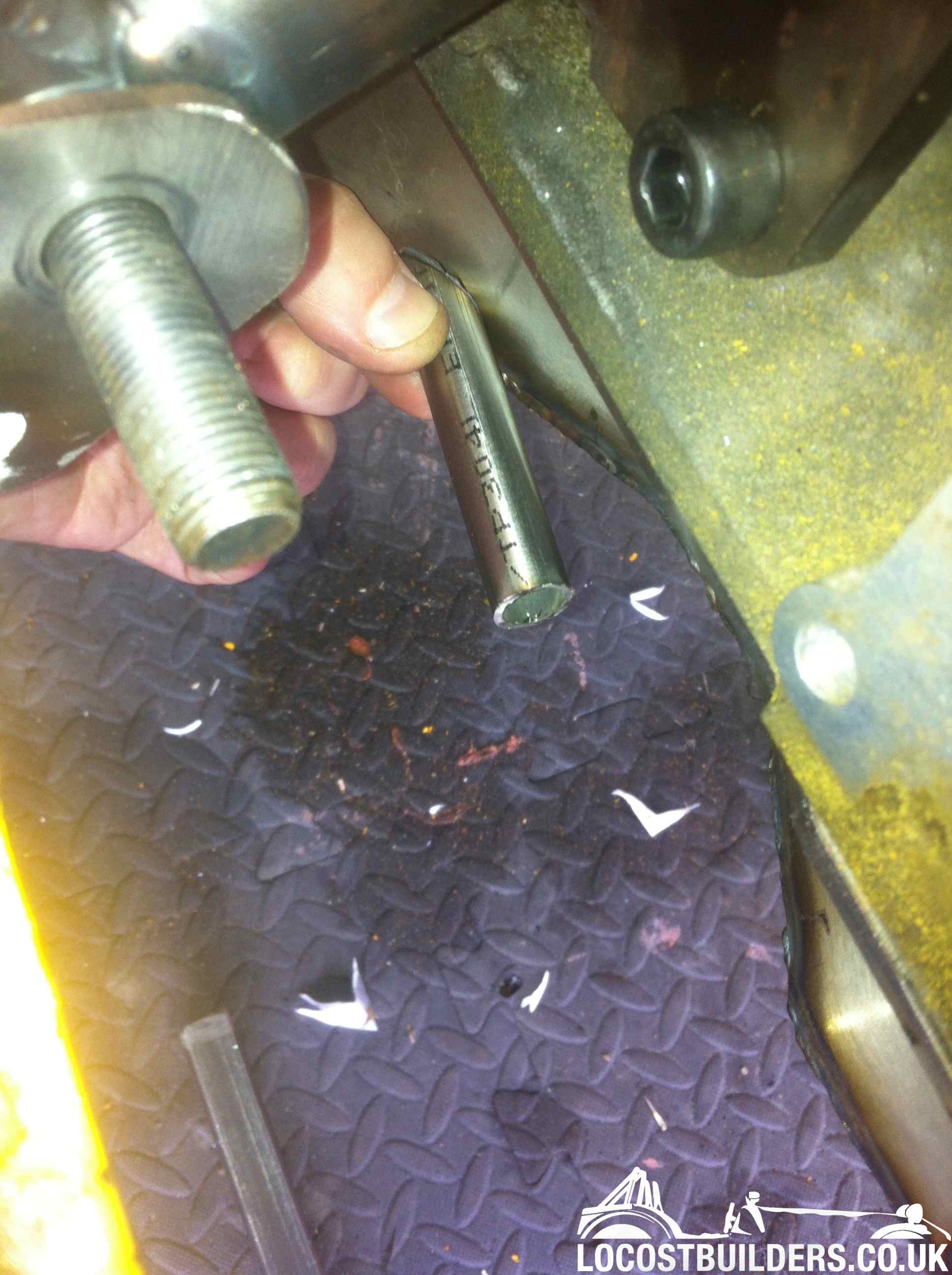
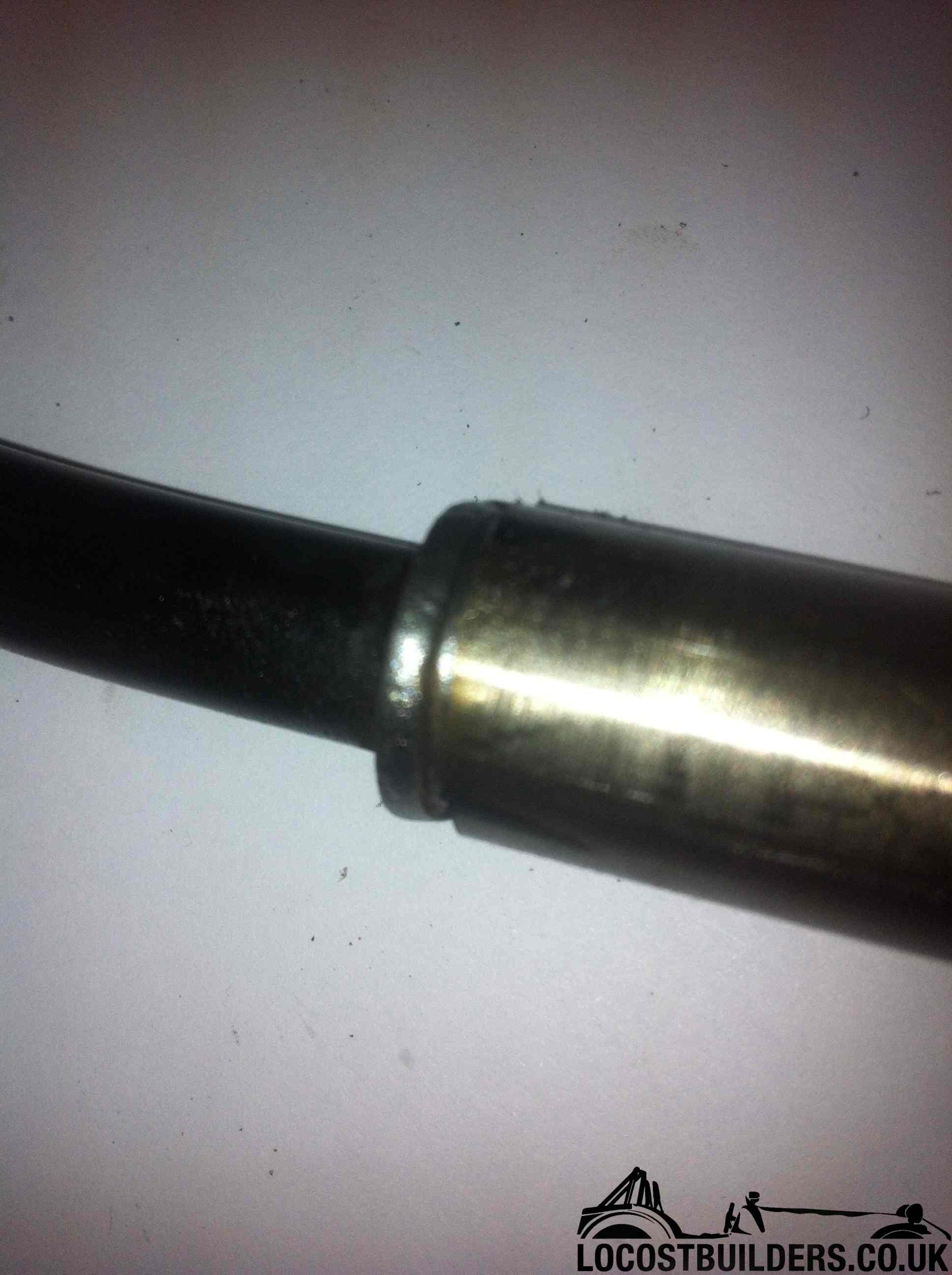 Next came the plan to fit the dipstick tube onto the sump take-off pipe. When measured, the tube is about 0.3mm short of half an inch, and the ID of the pipe is about 11.5mm, and i happen to have had my trusty 1/2 inch reamer ready. In order to make the dipstick pipe fit the sump, I reamed out the end of the take-off pipe to 1/2 inch. This was a little tricky, needing to position and clamp the pipe in the drill-vice, and then gently ream down and back (lots of cutting spray) in order to take it out. The end result is that the dipstick tube fits nicely into the end and has a little swivel room.
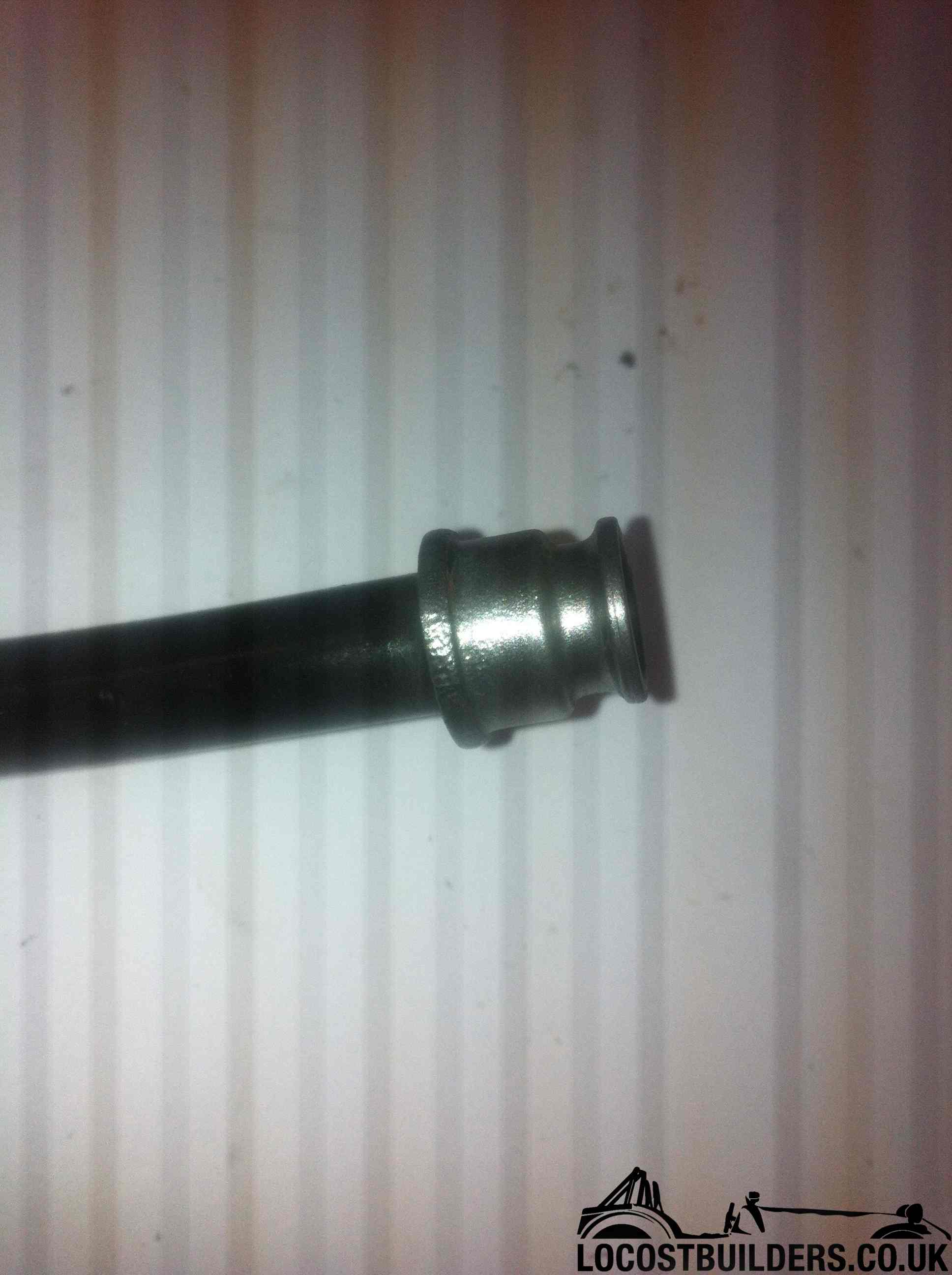 I also cleaned the end up ready for welding. However, I decided not to weld it straight away for a couple of reasons: firstly, there’s no going back after putting that tack in, especially if it’s routed wrongly, and secondly I’d also be welding stainless to mild. In the end, I decided that the better solution by far would be to fit it all back to the car, make a support bracket for the tube so it hugs the engine nicely, and then epoxy it in. It will be a very strong solution, easier than a weld, and will give me a couple of minutes wriggle time before it goes off.
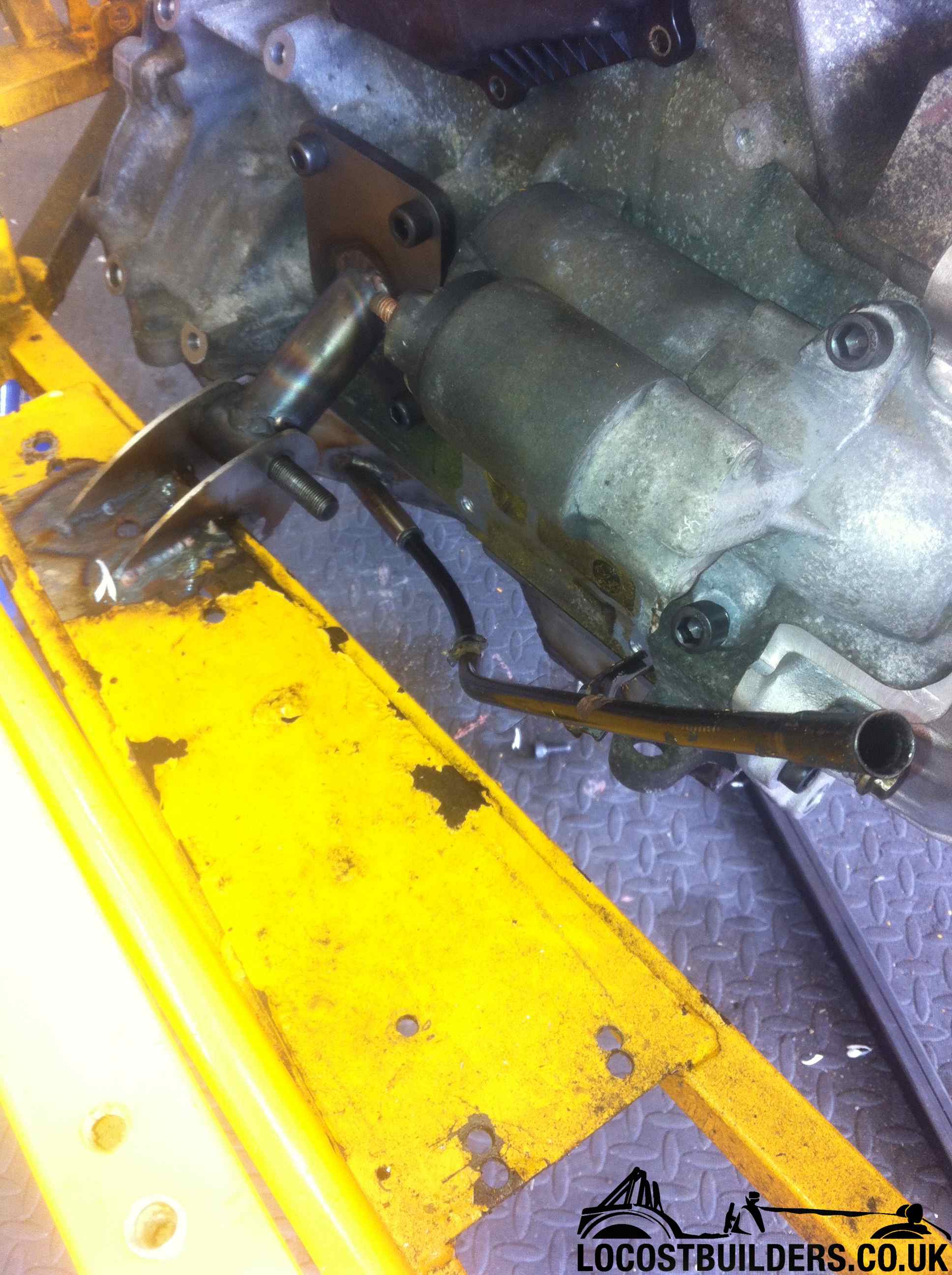 Here’s the final run up through the void. In the background middle-right you can see the starter motor bolts, and i’m going to fabricate a bracket to go onto this bolt as well – job done – dipstick now properly secure.


